Product Descriptions
Flame-Retardant and HFFR Compounds
Halogen-Free, Highly Filled and Reliable Compounding Solutions
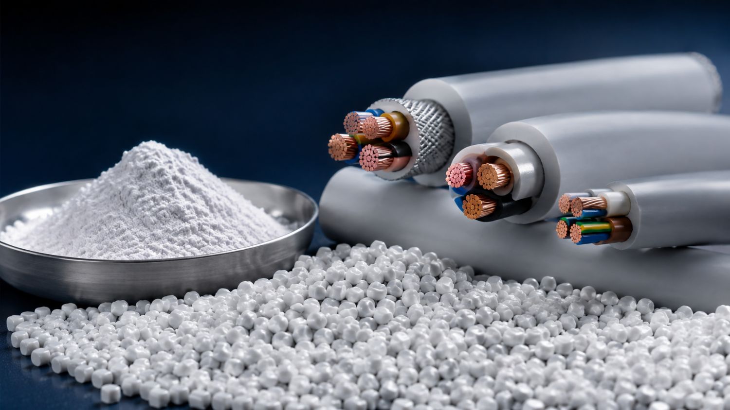
Flame-retardant plastic compounds are specially formulated materials designed to reduce fire risk, limit flame propagation and improve the safety performance of finished products. Demand for these compounds continues to grow across the construction, cable, electrical and electronics, automotive, railway, aviation, marine, household appliance and technical plastics industries.
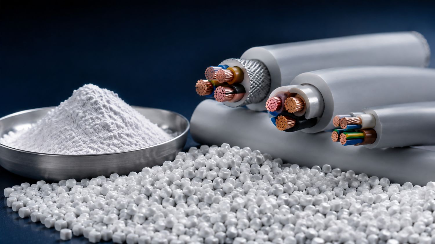
HFFR (Halogen-Free Flame Retardant) compounds are developed as alternatives to flame-retardant systems based on halogens such as chlorine and bromine. Widely used in the cable industry, HFFR compounds are preferred for applications in which limiting flame spread, reducing smoke density and minimising the formation of corrosive gases during a fire are important objectives.
Producing an HFFR compound is, however, a demanding compounding process. Large quantities of mineral filler must be distributed uniformly throughout the polymer matrix, and mineral loading may reach 60-80% in certain formulations. The compounding system must therefore provide reliable feeding at high filler levels, effective dispersion, controlled processing temperatures, efficient energy use and stable production performance.
Polmak Plastik offers process, machinery and application solutions for the production of highly filled flame-retardant and HFFR compounds based on Farrel Pomini Compact Processor technology.
Where Are HFFR Compounds Used?
The principal applications for flame-retardant and halogen-free compounds include:
Power, control, communication and data cables
Cable sheathing and insulation
Building and infrastructure systems
Electrical plugs, connectors and control panels
Electronic equipment and circuit components
Automotive cables and technical automotive parts
Railway and metro systems
Aviation and marine applications
Insulation panels
Pipe and profile applications
Household appliances and consumer electronics
Technical plastic components used in offices and living spaces
The selection of the carrier polymer, mineral flame retardant, binder, compatibiliser and processing additives directly influences the mechanical, electrical, thermal and flame-retardant properties of the finished compound.
Mineral Flame Retardants Used in HFFR Formulations
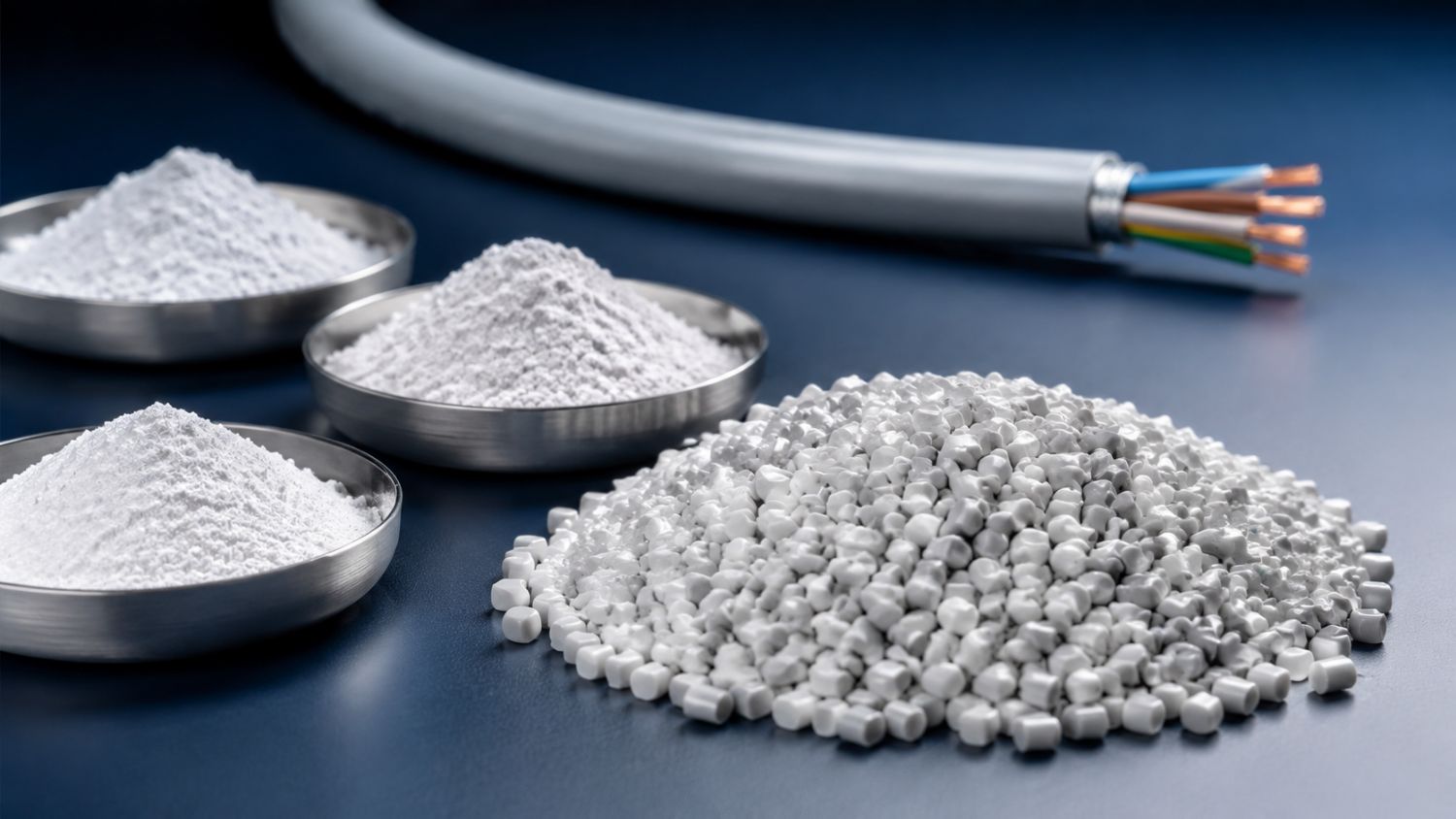
Metal hydroxides and natural mineral blends are commonly used in HFFR compounds. When exposed to high temperatures, these materials undergo an endothermic reaction, absorbing heat and releasing water vapour. This mechanism helps cool the combustion zone and restrict flame propagation.
Aluminium Hydroxide - ATH
Aluminium hydroxide, also known as aluminium trihydrate, is a widely used mineral flame retardant, particularly in PE/EVA- and EVA-based cable compounds.
According to Farrel Pomini Compact Processor application data, ATH compounds may have the following characteristics:
Mineral loading of approximately 60-63%
PP/EVA blends or EVA carrier resins
Mineral particle sizes of approximately d50 1.0-1.3 µm, depending on the application
Measured specific energy consumption of approximately 0.120-0.129 kWh/kg
Typical processing temperatures on the Compact Processor below 180°C, depending on the application
ATH activation temperature above 200°C
Because ATH is sensitive to thermal decomposition, its processing temperature must be controlled carefully. Excessive temperatures may cause premature reaction, moisture generation, surface defects and changes in final product properties.
Magnesium Hydroxide - MDH/MOH
Magnesium hydroxide may be preferred in polymer systems requiring higher processing temperatures than ATH can accommodate. It can be used at high loading levels in PP-, LDPE- and EVA-based compounds.
Compact Processor application data include the following results:
Magnesium hydroxide loading of up to approximately 70-80%
PP or LDPE/EVA blends used as carrier resins
Loading levels of 70-75% in PP formulations using MDH with a d50 of 4 µm
Loading levels of 75-80% in LDPE/EVA formulations using MDH with a d50 of 12 µm
Specific energy consumption of approximately 0.108-0.155 kWh/kg, depending on the formulation
Typical processing temperatures on the Compact Processor below 230°C
Magnesium hydroxide activation temperature above 330°C
Its higher activation temperature may make MDH suitable for polymers that require higher processing temperatures.
Huntite and Hydromagnesite Blends
Natural mineral blends based on huntite and hydromagnesite may also be used in halogen-free flame-retardant compounds. Because these minerals decompose at different temperatures, they can contribute to a progressive flame-retardant effect.
Application data indicate:
Mineral loading of approximately 70-75% in an LDPE carrier
An average mineral particle size of approximately d50 3.3 µm
Specific energy consumption of approximately 0.093-0.095 kWh/kg
Typical processing temperatures on the Compact Processor below 180°C
Hydromagnesite activation above 220°C
Huntite activation above 450°C
Challenges in Producing Highly Filled HFFR Compounds
Mineral flame retardants may account for a substantial proportion of an HFFR formulation. These high loading levels create processing requirements that differ considerably from those encountered in conventional plastic compounding.
The principal challenges include:
Feeding large volumes of mineral powder consistently
Achieving a homogeneous distribution of polymer and mineral
Breaking down mineral agglomerates
Ensuring adequate wetting of the filler by the polymer
Removing air and moisture from the formulation
Controlling high viscosity and torque levels
Protecting the polymer and flame-retardant mineral against excessive heat
Maintaining the required mechanical properties
Achieving consistent pellet quality
Limiting wear on screws, rotors and barrels
Reducing cleaning time during product changes
By separating the mixing and extrusion functions, the Farrel Pomini Compact Processor helps manufacturers manage these demanding process conditions.
Farrel Pomini Compact Processor Technology
The Compact Processor system consists of two principal units:
Farrel Continuous Mixer
Single-screw hot-feed extruder
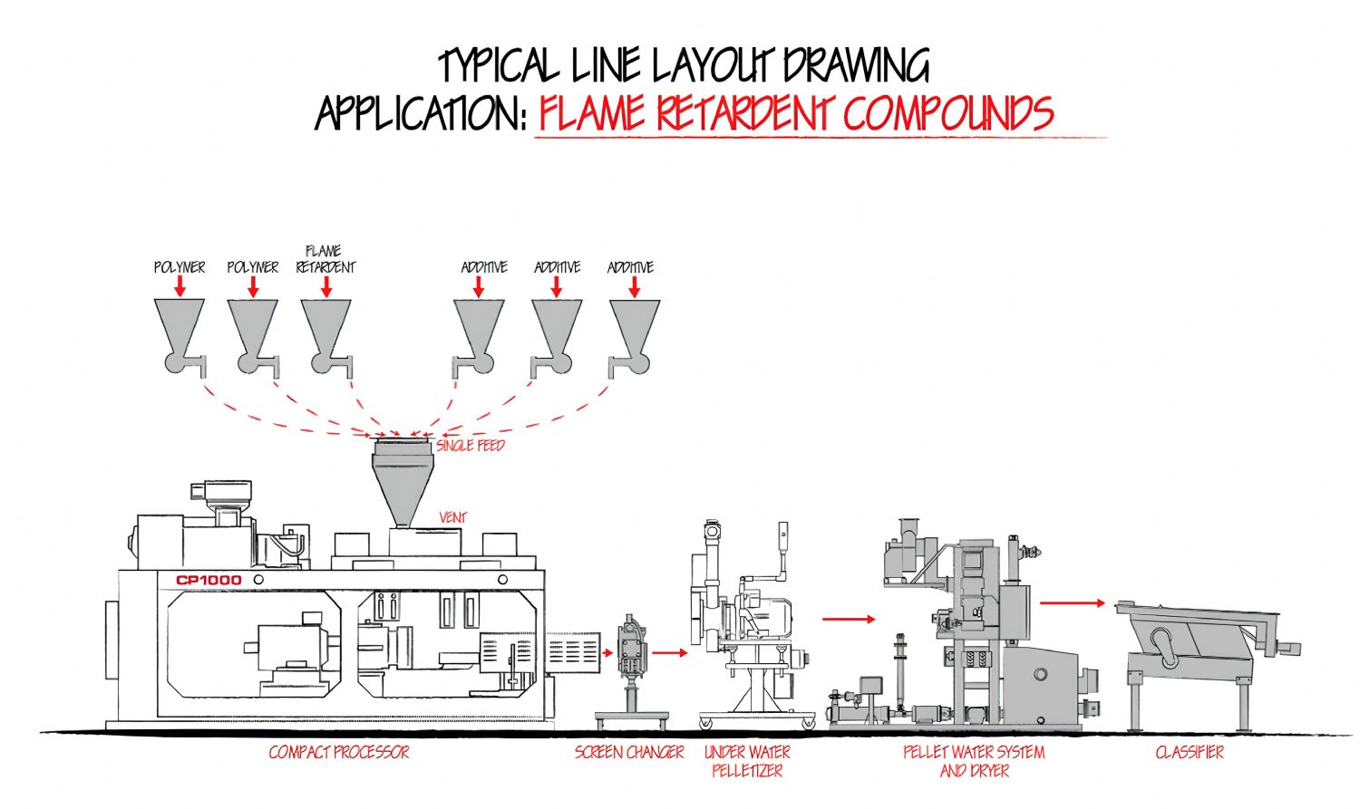
The Continuous Mixer melts the polymer and disperses the mineral fillers and other additives. The homogeneous material leaving the mixer is transferred to a short single-screw extruder, which develops the pressure required for filtration and pelletising.
Separating mixing from pressure generation provides a broad process-control window, particularly for highly filled and temperature-sensitive formulations.
Operating Principle of the Continuous Mixer
The Farrel Continuous Mixer contains two non-intermeshing rotors that rotate at equal speed in opposite directions. The rotors are supported at both ends, and the unit operates under starve-fed conditions.
After the polymer and additives enter the mixing chamber, the forward flights convey and compact the materials. As heat and mechanical energy alter the viscosity of the polymer, the formulation progresses through the mixer.
A reverse-helix section in the rotor geometry directs part of the molten resin backwards, bringing it into renewed contact with partially molten material and creating intensive mixing. A neutral pumping section then assists the discharge of the homogenised compound through the mixer orifice.
Dispersive and Distributive Mixing
Successful HFFR production requires both dispersive and distributive mixing.
Dispersive Mixing
Dispersive mixing breaks down mineral agglomerates and distributes them as smaller particles within the polymer. In the Compact Processor, this action occurs in the high-shear region between the rotor tips and the wall of the mixing chamber.
Each passage through this zone exposes the material to high local stress. The degree of mixing can be controlled through parameters such as rotor speed, the number of passes through the high-shear zone, process temperature and orifice position.
Distributive Mixing
Distributive mixing ensures that minerals and additives are distributed homogeneously throughout the complete volume of the compound. In the Compact Processor, material transfers from one half of the mixing chamber to the other. Backflow from the reverse helix towards the forward helix further supports distributive mixing.
The combined action of these two mechanisms helps achieve a homogeneous compound structure and consistent pellet quality, even at high mineral loading levels.
Low-Pressure Mixing and Effective Venting
The Compact Processor mixer operates at low pressure. Because the main feed opening is not completely filled, air and gases entering with the raw materials can escape through the same opening.
Depending on the system configuration, an additional downstream atmospheric vent may be incorporated. This allows trapped gases that could reduce feeding capacity or create voids in the product to escape.
The low-pressure process design may reduce the need for a separate decompression zone or a vacuum system on the mixer in certain applications. When more intensive degassing is required, the single-screw extruder may be configured as a two-stage, vacuum-vented unit.
Flexible Process Control
The following principal variables can be adjusted independently while the Compact Processor is operating:
Production rate
Rotor speed
Machine temperatures
Discharge-orifice position
Extruder speed
Feed rates
Adjusting the orifice opening controls the working volume inside the mixer and the mechanical energy transferred to the material. Reducing the opening may increase the material volume and energy input in the mixer, while increasing the opening can help reduce residence time and energy input.
This flexibility enables formulations with different mineral loading levels and carrier resins to be processed on the same system without extensive mechanical reconfiguration.
Rotor Options and Mixing Dams
The Compact Processor can be equipped with rotor geometries suited to different applications. General-purpose rotors may be combined with rotor designs intended for shear-sensitive or highly mineral-filled products.
Mixing dams installed in the chamber barrel create an additional shear area between the rotors and can improve dispersion. These dams can be installed or removed in approximately 5-10 minutes.
The three-piece rotor construction allows an alternative rotor design to be installed in approximately one hour, making the system easier to adapt to different HFFR formulations and product requirements.
Example Process Performance for HFFR Production
A reference application study prepared for the CP550 Compact Processor considered a PE/EVA-based cable-sheathing compound containing 60% ATH.
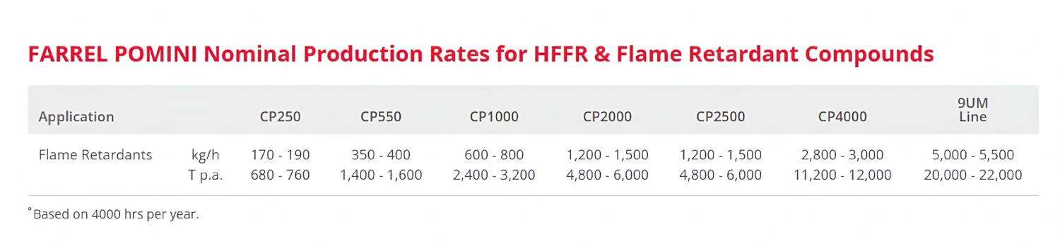
The indicated production rate for this application was approximately 350-500 kg/h. The general application-dependent output range stated for the CP550 used at the Farrel Pomini development laboratory is approximately 300-700 kg/h.
For higher-capacity production, a CP2500 Compact Processor equipped with a hydraulic screen changer and underwater pelletising system can be configured for a typical output range of approximately 2,000-3,400 kg/h.
These figures are provided for reference only. Actual capacity and process parameters depend on the mineral type, particle size, loading level, carrier polymer, melt-flow index, additive package, required pellet quality and feeding system. The final machine configuration should be confirmed through laboratory trials using the customer's formulation.
Single-Screw Extruder and Pelletising Options
The homogeneous compound discharged from the mixer is fed hot into a single-screw extruder. The standard extruder uses a short pumping screw with an L/D ratio of approximately 11:1.
Depending on the application, the system may incorporate:
Different screw geometries
Alternative compression ratios
A two-stage, vacuum-vented extruder with an L/D ratio of up to 19:1
A hydraulic screen changer
A strand pelletising system
An underwater pelletising system
The short extruder geometry helps generate the required pressure without subjecting the fully mixed compound to unnecessarily long thermal exposure.
Feeding System
In HFFR formulations, polymer pellets, mineral powders, process additives and certain liquid components must be introduced through accurate dosing systems.
The Compact Processor line can be equipped with gravimetric loss-in-weight feeders. Up to six separate feed streams, including one liquid stream, may be incorporated into the system.
Feeding all dry materials through a single main inlet can:
Reduce the complexity of the feeding system
Limit the need for additional side feeders
Reduce the number of components exposed to wear
Simplify formulation changes
Help shorten line-cleaning times
The primary liquid feed port can be located above the forward-helix section of the rotor, while a secondary liquid feed port may be positioned in the following mixing segment.
Advantages of Compact Processor Technology
High Mineral Loading Capacity
The large free volume of the mixing chamber enables the processing of formulations with mineral loading levels reaching approximately 60-80%.
Controlled Processing Temperature
The relatively large clearances around the rotors and mixing chamber help reduce the risk of local overheating. This is especially important for temperature-sensitive minerals such as ATH and for PE/EVA carrier systems.
Efficient Energy Use
The mixing process normally operates adiabatically, with a significant proportion of the energy required to melt the material transferred directly by the rotors. Lower external temperature input, a large free volume and a short residence time can help reduce overall energy consumption.
Improved Dispersion
Controlled dispersive and distributive mixing helps distribute the mineral more homogeneously throughout the polymer. Effective dispersion is important for mechanical properties, surface quality and product consistency.
Formulation Flexibility
Production rate, rotor speed, temperature and orifice position can be adjusted during operation. This reduces the need for extensive mechanical changes when switching between different formulations.
Low Wear and Easy Maintenance
The mixing chamber uses replaceable tool-steel liners and a three-piece rotor system. Rotor protection options include hard-chrome plating, thermally sprayed tungsten-carbide coatings and specialised hard-surface treatments.
The hinged, clamshell mixing chamber provides rapid access to the rotors and internal surfaces, helping reduce the time required for cleaning, inspection and maintenance.
Easy Automation and Line Integration
The Compact Processor is managed through a PLC-based control system and touchscreen operator interface. It can be integrated with:
Gravimetric feeders
Screen changers
Pelletising systems
Auxiliary process equipment
Supervisory SCADA systems
Remote connectivity options can also facilitate process and service support.
Compact Processor Model Range
The Compact Processor family can be scaled from laboratory and lower-output production to high-capacity industrial compounding lines.
The principal models include CP125, CP250, CP550, CP550XL, CP1000, CP1000XL, CP2000, CP2000XL, CP2500, CP2500XL, CP4000 and CP4000XL.
The appropriate model should not be selected solely on the basis of target capacity. Mineral loading, bulk density, carrier polymer, target specific energy, feeding characteristics, degassing requirements, filtration needs and pelletising method should all be evaluated together.
Application-Specific HFFR Lines from Polmak Plastik
For investments in flame-retardant and HFFR compound production, Polmak Plastik focuses on the correct configuration of the complete process rather than machine capacity alone.
The following information is considered during project evaluation:
Carrier polymer type
Type of mineral flame retardant
Mineral particle size and surface treatment
Target mineral loading
Additive and processing-aid content
Required production capacity
End-use application
Required mechanical and electrical properties
Applicable cable or fire-performance standard
Required pellet size and cutting method
Degassing and moisture-removal requirements
Filtration sensitivity
Automation and recipe-management requirements
Based on the formulation data, the appropriate Compact Processor model, rotor combination, extruder configuration, feeding system, screen changer and pelletising equipment can be selected. Where required, laboratory trials can be performed to confirm production capacity, product temperature, specific energy consumption and pellet quality.